Menu

Show posts

This section allows you to view all posts made by this member. Note that you can only see posts made in areas you currently have access to.

Show posts Menu

Messages - Johannes @ Robots in Architecture

#1366
Support / Re: How can I use a customized tool ?
May 06, 2014, 08:20:06 PM
Hello Bogdan,

Sure, that shouldn't be a problem. Are you using a KUKA robot or are you mostly simulating processes at the moment? Because if you've got the tool measured in at the robot, it would be good to have the XYZABC values.
Basically the Custom Tool component works in a way that you insert mesh geometry, then right-click it, go into the settings, enter the XYZABC values, and click confirm. If you're having problems it's probably because you didn't set the XYZABC values?
While it does give you the appropriate error message when you click on the message balloon in the upper right corner it's rather hidden. I've just implemented a new, more clearer message, it will be part of the member version soon.
Some more things:
Usually we assume that the tool axis of the mesh should be in positive X direction, the XYZABC values (if you are working "virtually") are offset values, so you can easily measure them from the 3D model (also refer to the graphic in the Custom Tool settings).

Let me know if it works, if not please also attach your 3D model. If it's confidential you can also eMail it to johannes@robotsinarchitecture.org

Best,
Johannes

#1367
Tutorials / Tutorials Updated
March 26, 2014, 12:11:11 AM
The tutorials have been updated to work with the most recent release of KUKA|prc and Grasshopper. Ideally update your KUKA|prc installation if you haven't done so already.
If you for any reason still need the old version of the tutorials, please contact johannes@robotsinarchitecture.org

Best,
Johannes
#1368
Hello Wassim,

First of all, you need to create a custom tool geometry as single mesh - i.e. you can model it in Rhino, mesh it, and then join the meshes.
At the robot, every tool is defined by XYZABC values defining the offset from the flange. In your case, with the tool 102mm away from the robot's flange it would be XYZ would be 0/0/102. If you set ABC to 0/-90/0 and define the robot's position via a plane, the plane's Y-axis will be the wire and its Z-axis will face towards the robot's flange.
Of course you also have to set the same tool values at the robot itself (Start-Up/Calibrate Tool/Numeric Input, see p.109 of the KUKA KSS 8.2 manual)
The tricky thing with hotwirecutting is defining the best direction from where the robot holds the hot wire to optimize reachability.
I've attached an example-file to this post.

One more thing: 102mm seems like a very small wirecutter for a KR60HA - are you sure about that? If it's 102cm then you have to use 0/0/1020 for XYZ instead. In the example I used an Agilus with a tiny wirecutter :)

Best,
Johannes

P.S.: I'm on the train at the moment and couldn't watch the video - will do so ASAP.
#1369
Support / Re: Start/End Position
February 14, 2014, 09:58:16 PM
Hello,

The Start and End position refers to the "absolute" start/end position, i.e. from where a robots starts a SRC file and where it ends. You can choose to end with a HALT position instead if you e.g. want to end with the last LINear movement command.

If you are using the most recent member version, the start and end simulation is simulated in the regular robot simulation. In the trial version, you have to enable smooth simulation and add a slider to the smooth simulation input to see the first and last position.

Don't hesitate to contact us if you've got any further questions or need an example file.

Best,
Johannes
#1370
...actually I can guess the institution from your eMail address. UMichigan is a member and I'll unlock the account in a minute!
Best,
Johannes
#1371
Sure, we have to unlock you as a member of the Association for Robots in Architecture. From your username I cannot guess your institution, so just send me an eMail to johannes@robotsinarchitecture.org and I'll crosscheck it with our records.
The members section is only visible to verified members of the Association for Robots in Architecture - a membership is usually valid for a year and is 350EUR for institutions/professionals and 75EUR for students (in both cases allows the use of KUKA|prc for research and teaching and the Rob|Arch books for private use).

Best,
Johannes
#1372
Hello,

First results seemed fine, but I only checked it on a KR16. I should have time again tomorrow. Can you give me the version number that you're using? Go into the KUKA|prc settings and to the About section. It's in the upper right corner.
A general workaround, as we had at least similar problems before, that the A04 didn't turn like in the simulation: Put the robot into a position close to the beginning of a job and write down the individual axis values. Then enter them as the KUKA|prc start values.
KUKA|prc is programmed to use the "shortest" way for PTP movements, i.e. it checks all alternatives and takes the easiest one. The internal KUKA solver sometimes chooses a different strategy. I'll put the possibility of defining the status/turn of the first PTP command into the next release.

Best,
Johannes
#1373
Great, thank you for the data. I'll be at our Agilus on Thursday and test it myself!

Best,
Johannes
#1374
Hello,

I don't see any problem here, but the issue is that the "physical' movement of the real robot differs from the virtual robot, right? In that case I would need a comparison with your real robot, i.e. some images and or a video! Please also note that the simulation can only be accurate if you use the same XYZABC values for the tool and base in both simulation and reality.

Best,
Johannes
#1375
EDIT: As this is post is viewed very frequently, here is some useful troubleshooting advice:

For an accurate simulation, the physical and digital robot have to be synchronized, i.e. tool and base have to use the same number and XYZABC value. Please refer to the sticky post on top of the forum: http://forum.robotsinarchitecture.org/index.php/topic,115.0.html
It is possible to set custom axis limits, which differ from the standard robot setup. If you change them back to default, make sure that there are no mechanical stops installed.
The simulation is only accurate until the first point that is out of reach. Do not depend on any information that comes AFTER an unreachable position, .e.g. when you manually skip an unreachable position via the smartPAD/KCP.
KUKA|prc only calculates the programmed positions, but there can be out-of-reach positions in between as well. You can enable LIN Interpolation in the settings to spot errors in between LIN movements.
Members are encouraged to use the most recent version of KUKA|prc - we usually update the software at least once a month.
Post in the forum or get in touch with johannes@robotsinarchitecture.org if the problem persists.

Thanks!


Hello,

First of all, this may of course be a bug, but I cannot diagnose this without the file (and preferably the robot).
Basically, it's important to consider that there is no "official" KUKA kinematics solver available for third-party software. The most accurate simulation you are going to get is via the combination of KUKA SimPro and OfficeLite, which is a virtualized robot controller, i.e. you put the KUKA|prc-generated KRL file there and can execute it virtually. So the KUKA|prc solver is made to best approximate the way KUKA robots behave.
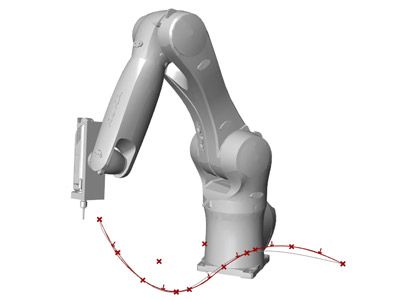
Regarding the A4 problems you can try to set the first position as a PTP movement with a specific Status value - e.g. 010, an explanation is in the KUKA Expert Programming Manual, should be on the included CD, see also the graphic below that shows the different ways how a robot can reach a defined position.


The fact that B is always 90 probably means that you've got only vertical positions (B is the rotation around the local Y-axis).

Best,
Johannes

#1376
Tutorials / Example: Extrusion Process
December 26, 2013, 04:53:12 PM
NOTE: This example uses an older version of KUKA|prc!


Title: Robotically Extruding Material along a NURBS CURVE
Level: Beginner
Description: Robot follows a NURBS curve tangentially as to extrude material.
Requirements: Rhinoceros 5, Grasshopper 0.9.0072, KUKA|prc

Refer to projects such as www.mataerial.com/#mataerial-in-action by Mataerial - but note that such processes are more complex than just the motion planning as shown in the Grasshopper example above. The ";KRL EXTRUDE START" command is just a placeholder, if e.g. the extruder is attached to the robot's digital output #33, you could use "$OUT[33]=TRUE" instead.

The example has been updated to use the most recent version of the KUKA|prc trial version!
#1377
Hello,

You are correct about the base and tool - you first have to calibrate the tool and base on the robot and then use the same number that was set at the robot inside KUKA|prc. The XYZABC values in KUKA|prc are only used for the simulation.
There is a particular reason for that - let's assume that a milling tool breaks and you have to put in a new one. If the values were hard-coded, you would have to go back into KUKA|prc and change them there again. As only the ID is referenced, you just have to save the new tool with the same tool-number.

By default we're using X as the tool axis in the tool definition - as in the KUKA manuals. If you go into the settings of the Custom Tool component, there is an illustration. However, you can use the Z-axis as well, there is an option in the KUKA|prc settings for it (though I'm not 100% sure if it's already available in the trial version).
If you're using planes as the input for movements, the planes' positive Z-axis will be the tool axis.

...so to sum things up: You assumed correctly!

Best,
Johannes
#1378
General Discussion / Re: Hello,
November 21, 2013, 10:30:41 PM
Sure, there you go:

KUKA|prc Core generates the KRL code (double-click it to go into settings and set an output directory, though), If you enable Collision checking (in the settings, Simulation tab) you can plug a mesh object into the COLLISION input input and KUKA|prc will check for collisions. The default tool is just the initial tool that will be used, e.g. one of the included spindles. Every tool you measure in at the robot will get a number - it's important that you give the tool you're using the same ID as how you saved it at the robot.
KINEMATIC is the output for the virtual robot component - KUKA|prc simulates only the end-effector, if you attach the Virtual Robot component you can also simulate the full kinematic movements of the robot.
Don't worry about the ENDEFFECTOR and ORIENTATION outputs, they are just geometry, if you need it e.g. for rendering or visualization.

The ENABLE toggle will go away in the next version, it's actually highly redundant with Grasshopper functionality as was a bad idea to start with... Anyway...
Also take a look at the existing examples in the Tutorials section, this should make the data flows clearer as well.

Hope this helps you along!
Best,
Johannes

P.S.: I've taken the liberty of renaming the topic to "Getting started with KUKA|prc" to make it easier for people looking for similar information.
#1379
General Discussion / Re: Hello,
November 21, 2013, 10:04:45 PM
Hello,

Good initial reading are the KUKA manuals, which you should have received with your robot (if not, I can send you a few) - this will make it easier to understand some aspects.
Basically, KUKA|prc works with the principle that you just queue up commands, mostly movements. There are several types of movement, e.g. linear, PTP, spline, circular (see manual for details) which require different inputs.
It's just essential to know that you need more data than just XYZ to define a robot position - XYZ is enough for a 3-axis CNC machine, a 5-axis machine already requires the definition of XYZ plus a tool axis. With the robot, you at least have to define XYZ, plus tool axis, plus the rotation around the tool axis (in KUKA|prc: orientation). So you either define a position via a plane (fulfills the requirements) or via three points, with the first base point defining the tool center point (XYZ), the second point the tool axis, and the third point the orientation around the tool axis. You can switch between plane mode and 3-point mode by right-clicking a movement component.
Even with the endeffector clearly defined, there are still 8 different ways how a robot could approach that positon (see status/turn in the KUKA manual).
If you want to have the robot follow a line, you either have to divide the curve into many planes, or into many "triplets" of points. Some of KUKA|prc components take care of the work (e.g. divide by distance, which requires a base curve, a guide curve, and an orientation point - it gets the base points from dividing the base curve, the guide points from dividing the guide curve, and the orientation from the point).

Hope this makes it a bit clearer!
Best,
Johannes
#1380
General Discussion / Re: Hello,
November 21, 2013, 04:21:39 PM
Hello!

No problem, I moved the topic!
It depends if you have got previous experience with Grasshopper and what you would like to do with KUKA|prc. You've already seen the tutorial section which is helpful for playing around with existing definitions, the first post there also contains a PDF tutorial. We also do quite a few workshops each year, though I can't provide any fixed dates for 2014 yet.
So what are your plans?

Best,
Johannes