Recent posts
#11
General Discussion / Re: E1 Value Control for 3d Pr...
Last post by luispacheco - July 21, 2025, 03:50:34 AMa good altenative that I have been using is storing a custom system variable, and then reading it from a connected mqtt server that streams to the extruder. Im happy to guide you on the setup if it helps.
#12
General Discussion / Re: E1 Value Control for 3d Pr...
Last post by Johannes @ Robots in Architecture - July 18, 2025, 08:55:07 AMHello Rodrigo,
Regarding the protocol, the shield would take care of it. Depending on how it is configured it will accept different data types, the most common one are unsigned integers. If that is the case, multiply the number by e.g. 100 before sending it and on the Arduino divide it by 100.
For the analog signal, be careful that the most industrial IO devices output either 0-10V or 4-20mA, and both will cause issues with an Arduino. You can try to limit the range on the 0-10V to something like 0-3V I guess, but lose a lot of resolution by doing so. Plus if something goes wrong the 10V might roast your Arduino.
And regarding the variable, I just can't look up the right variable now, probably something like $ACT_VEL.E1 for the E1's current speed - please take a look at the KUKA System Variable documentation. For WoV, there are plenty resources online, starting from KUKA's own documentation to YouTube (e.g. https://www.youtube.com/watch?v=CQom2cNDMt8)
Best,
Johannes
#13
General Discussion / Re: E1 Value Control for 3d Pr...
Last post by rshiordia - July 18, 2025, 01:33:05 AMThanks a lot Johanness!!!
I was completely unaware of the "Toggle External axis" option.
In your import_gcode example, I now see that the E1 value just grows and grows, so it's as though that value represents the actual length of plastic extruded.
I see how it would be very advantageous to have the robot deal with all the feeds and speeds while one only deals with that single number on PRC. That's actually great. I was not aware of what you meant by "position," but I think that's what it is. At the end of the code, E1's position is at some very large value, so that value is the actual length of plastic extruded.
However, since I don't have Kuka motors right now, that option is a bit off the table.
I feel that my easiest option (at least for my skill set) is to map the speed of E1 to an analog signal because I'm not aware of how the E1 position value would be sent via EtherCAT(I wouldn't know how to parse that on the arduino side, what type of protocol is the position being output in?).
What is easiest on the Arduino side is to use its analog-to-digital converter to control the speed of extrusion. So, an analog signal would be easier to deal with in Arduino for me.
Can you share a bit more on this mapping process? What do you mean with "looking for the according KRL variable for the speed of E1." Would that variable's value be in the sps.sub ??? or is it found somewhere in the output of PRC
I have no idea how to do this mapping, so it looks like I need to read up on setting that up on Work Visual (never used it). Perhaps you can share some resources on how to start learning that?
Many thanks!
Rodrigo
#14
General Discussion / Re: E1 Value Control for 3d Pr...
Last post by Johannes @ Robots in Architecture - July 17, 2025, 11:04:41 PMHello Rodrigo,
The advantage with an external axes is that the robot takes care of the synchronization of the movements. So E1 in your example will start exactly at a given position and at the end of the movement will be at the programmed target position. However, you need to use original KUKA motors for external axes.
What we did in the past was that we added a simulated axis in WorkVisual (tick the according box). On the robot, you have got the sps.sub, which runs in a permanent loop in the background, like a background thread. In the sps.sub, you can now get the actual position of E1 and e.g. map that to a signal that is connected to a microcontroller, which then controls your stepper motor in the extruder.
For connecting the Arduino, a nice way would be an EtherCAT shield like that: https://www.bausano.net/en/ethercat-arduino-2
That way, you just have got one Ethernet cable going to the Arduino with all the data.
Rather than the position of E1, you might only want to output the speed of the E1. Just look for the according KRL variable. A speed variable is also more easily mapped to an analog output, compared to an absolute position value.
All of the above needs good knowledge of WorkVisual, but nothing that is super hard to do.
In KUKA|prc, to set the E1 value, right-click the motion component and enable to option to show external axis values!
I hope that helps!
Best,
Johannes
#15
General Discussion / E1 Value Control for 3d Printi...
Last post by rshiordia - July 17, 2025, 10:48:01 PMHello all,
I'm writing to you with a question regarding the E1 value that is used in the 3d printing component of Kuka |PRC. I hope you can help if you have the time, or point me in the right direction.
I understand that E1 value is used to control the velocity of the extruder when 3d printing. (not the velocity of the motion of the extruder head, rather the actual extrusion rate from the extruder, e.g., how much plastic is coming out of the nozzle)
We've developed our 3d printing pellet extruder. Our extruder is a stepper motor controlled by an Arduino. So far, we've just had a single digital output on the robot, turning it on and off by inserting $OUT [14]=TRUE whenever we want to turn the extruder on and off. This is easy to do in PRC with the KRL as a text component. We can turn it on and off directly now that we've figured out how to use the digital outputs of the robot. We have the output drive a relay that tells the Arduino to start or stop extruding, so the digital output is very isolated from the extruder electronically.
However, we are now developing a more complex setup where we want the robot to control the velocity of the extruder, the stepper that drives the extrusion needs to go slower or faster depending on the geometry, layer length, etc. This way we can extrude faster on corners or slower in short layers. I can tell that in other setups, this is being done with an E1 value that is kind of like an external axis value on the import G-Code 3d printing component. I think the AIBuild software also does this with the E1 value, but I'm not sure.
I'm a bit lost on what to do with that E1 value on the robot side. I have several questions regarding this:
1-Could we use KRL text like $OUT [14]=0.5 to use an analog output directly? I could just parse this in GH and use the output to directly drive my Arduino-based extruder (with proper connection to the voltage of Arduino).
2- How to use the E1 value in other components other than the import gcode? LIN, PTP, etc always output E1, E2,... E4 to 0 when you don't have an external axis, so they are being used. I could parse it manually in Grasshopper, having the output from LIN motion and inserting whatever value I want on E1. Is this a good idea?
3-Regardless of the software side, I also wanted to ask you if you can point me in the right direction for the robot side requirements for such a setup:
3.1- How to do the mapping of E1 to an analog output ( or the external axis output) on the robot? It looks like it has to do with the $config.dat file. What do I need to do on the robot side to use the E1 value to control the extruder speed?
3.2 Can you share some more information on how to use and connect the analog outputs or external axis signals to the extruder? We have a KR30-3 and a KR10 Agilis Sixx for these applications, so I just wanted to know if you could share some quick tips on how to connect my extruder, which is Arduino-based. However, I can use the Arduino analog inputs (with a step-down module, I think) to control the extrusion speed.
My vision is to eventually have a LIN++ command on PRC that would take the "target as plane" and "speed" inputs, along with an extrusion rate. This would then output the KRL line with all the XYZ values and the E1 with the extrusion rate. On the robot, the E1 value would control how much plastic is coming out of the nozzle. This way I would be doing my slicing on GH as I've been doing for years, but with more control over extrusion rate.
Many thanks!
Rodrigo
#16
Support / Re: keeping the tool oriantati...
Last post by Johannes @ Robots in Architecture - July 10, 2025, 10:44:41 PMHello,
First of all, thank you for the excellent preparation of the file, with nicely internalized planes and without tons of external plugins.
Fortunately the error was easy to spot, at the very beginning you decompose the planes to calculate the angle for the rotation. In your file, you calculate the angle between the Z-axis of the target plane and the global X-axis. Because the Z-axis changes in tilt, you get the change in orientation.
Using the Y-axis instead makes it consistent, in my testing.
Best,
Johannes
#17
Support / keeping the tool oriantation c...
Last post by OXIDO - July 10, 2025, 12:51:57 PMHello,
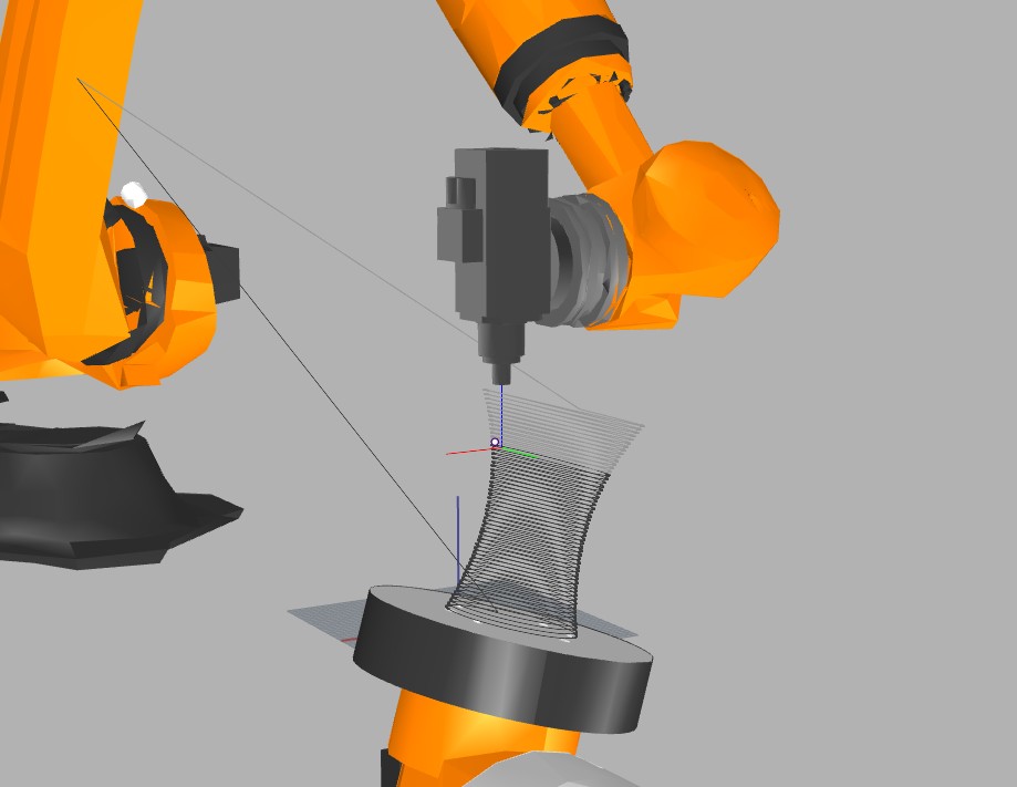
I'm having trouble keeping the tool in one position. The tool starts working on +x and then, between 0.4 and 0.5 (Simulator Slider), it rotates and orients to -x. This movement is causing visual defects in the piece. Does anyone have a solution for this?
0 to 0.4
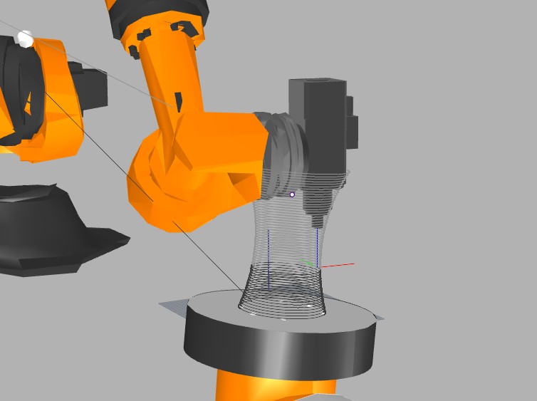
0.5 to 1
Regards,
Ojas
I'm having trouble keeping the tool in one position. The tool starts working on +x and then, between 0.4 and 0.5 (Simulator Slider), it rotates and orients to -x. This movement is causing visual defects in the piece. Does anyone have a solution for this?
0 to 0.4
0.5 to 1
Regards,
Ojas
#18
Support / Re: Setting Up DKP400 Virtual ...
Last post by GATECH_DFL - June 04, 2025, 11:25:24 PMRhino file for above ^ (accidentally did not attach both).
#19
Support / Re: Setting Up DKP400 Virtual ...
Last post by GATECH_DFL - June 04, 2025, 11:24:33 PMThank you for the response. I'm still having a lot of trouble removing these unnecessary movements, some of which are resulting in singularities or collisions. I've attached file here if you could look and tell me where I need to adjust? The robot also does some of these extra movements in the simulation.
#20
Support / Re: Setting Up DKP400 Virtual ...
Last post by Johannes @ Robots in Architecture - June 04, 2025, 11:41:03 AMHmmm... The easiest way might be to use axis movements in between larger movements.
So the robot finishes a path, moves in Z away from the object, makes a PTP movement to a safe position while the turntable rotates, then moves back and continues your linear motion paths.
You will need to identify paths with significant repositioning time (e.g. by comparing the E1 values), because if it just moves 20mm, then in turn the PTP motion is a major waste of time.
Best,
Johannes